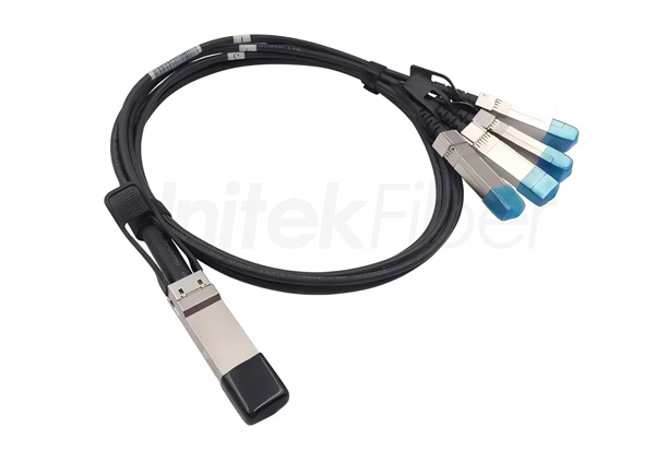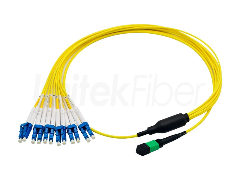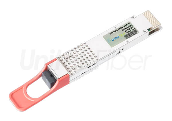
Data center fiber cabling system
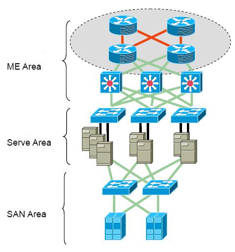
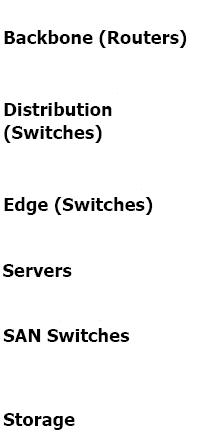
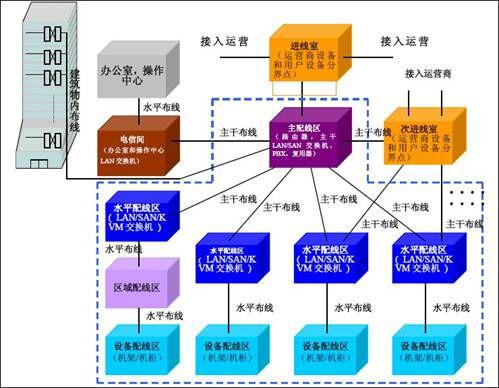
 The data center equipment cabling system consists of two parts: the SAN network cabling system and the network cabling system. It is one of the important contents of the computer room project. In the computer room system, the various wirings in the computer room must be planned and designed in a unified manner. The routing of the wiring bridges should be considered together with other various pipelines and bridges in the equipment room to ensure the reasonable and orderly implementation of the various systems in the equipment room. The data center integrated wiring project realizes redundant wiring management with its flexibility and expandability. The entire structured wiring system should completely avoid the occurrence of single point failure.
The data center cabling system uses: plug-and-play, high-density, scalable, pre-terminated cable system solutions with modular system management and pre-terminated components to reduce installation time. It enables data center fiber optic networks move, add, and change faster. The system's full range of fiber optic products can use low-loss fiber connectors and bend-insensitive fibers (bending radius < 7.5mm) to achieve smaller trunk cable attenuation and bending performance.
Quickly respond to any movement, increase and change of the network:
In the main distribution area of the data center, centralized wiring and star network wiring are adopted, which facilitates the wiring change of the data devices on the panel, and realizes the perfect integration of the physical layer and the application layer in the trunk wiring area.
Saving wiring space and installation time:
It has been proven that the high-density fiber optic cabling system can reduce the large congested cables in the routing route and save more than half of the space compared with the traditional cabling system. The factory-prepared high-density MTP/MPO trunk cable simplifies network deployment and saves 80% of the installation time of traditional fiber.
Support future web applications:
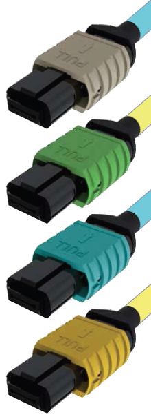
Optimized 50/125um (OM3, OM4) fiber optic networks with high-bandwidth lasers provide a wide space for high-speed applications, which enables flexible transmission of serial and parallel signals. Parallel fiber technologies such as high-speed interconnects and the currently used 40G/100G Ethernet are based on MPO backbone cable systems.
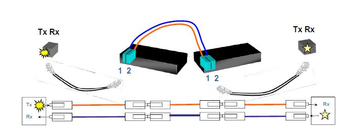
In order to support a two-way communication system using separate fibers, the wiring system should provide and maintain the correct signal. Polarity: that is, the transmission from one end of the link to the other end. Maintaining the correct transmission to the polarity through the cabling system is critical to the operation of the entire communication system.
Polarity A(10G)
Polarity A uses MPO straight-through pre-end trunk cable to connect to the pass-through module. The two ends use different duplex jumpers. One end uses a straight-through jumper and one end uses a cross jumper.
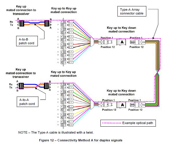
The advantage of this solution is that the trunk is simple to expand. The defect is that two different fiber optic jumper are used at both ends, which makes wiring messy.
Polarity A(40G)
Polar A (40G) uses a straight-through MPO pre-end trunk cable to connect the pre-end extension cables at both ends. The MPO pre-end extension cables at both ends have different polarity. One end is selected for straight-through and one end is selected for complete crossover.

Polarity B(10G)
Polarity B (10G) uses a cross-pre-ended trunk cable with the same jumper at both ends.
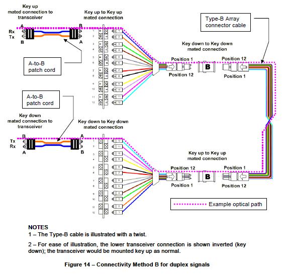
Polarity B(40G)
Polarity B(40G) uses a cross-pre-terminated trunk cable with the same jumper at both ends.
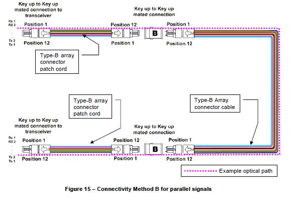
This solution is easy to operate and does not feel any polarity problems. The defect is that the single mode 8° angle solution is not supported.
Polarity C (10G)
Polarity C(10G) use several pairs of cross-trunk cables, straight through modules, and use the same jumper at both ends.
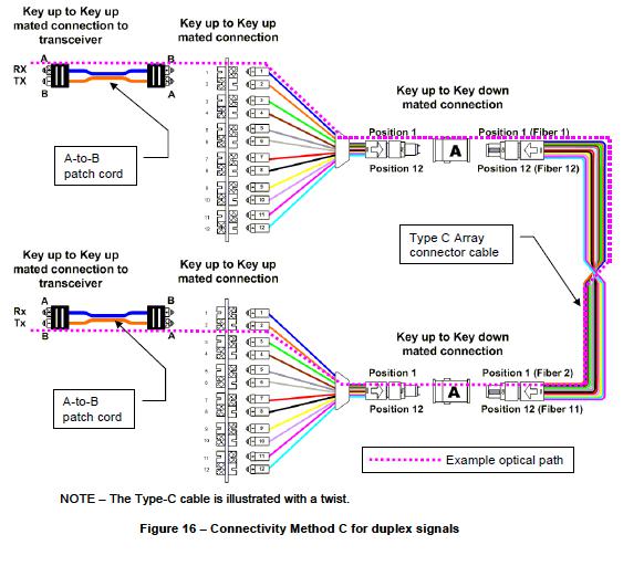
This solution is easy to use. The defect is that the backbone cannot be expanded and has great limitations.
10G standard link
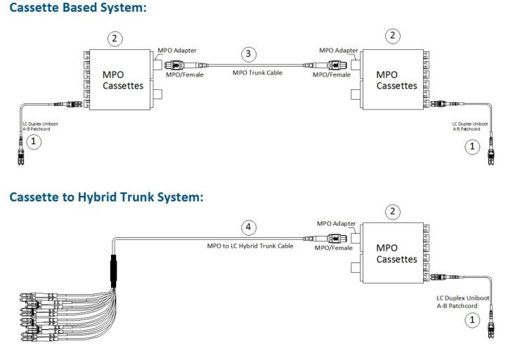
Link loss: standard loss (10.3 + 20.6) *2+ 3L*0.0035<2.6dB, common control needs to be 2.2dB.
10G multiple links
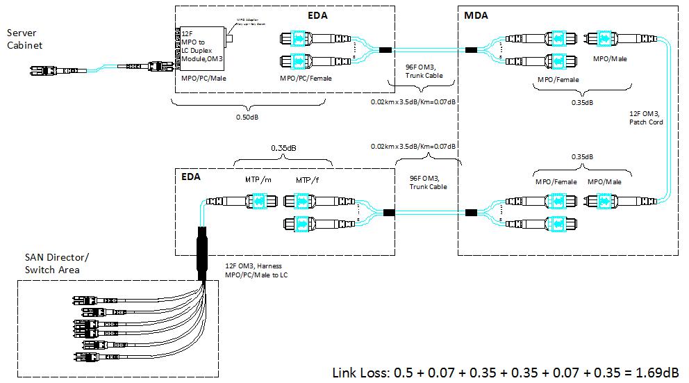
This link must use low loss MPO and LC fiber connectors.
40G Standard Link
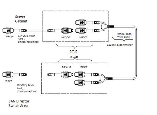
Link loss: normal loss (0.7+ 0.7) + L*0.0035<1.9dB, common control at 1.5dB.
40G multiple links
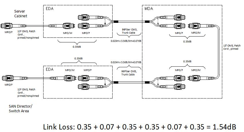
This link must use low loss MPO

