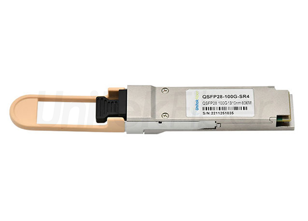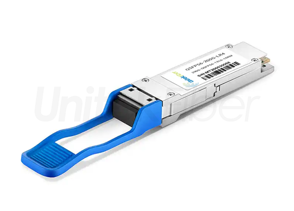
Optical transceiver undergo rigorous testing and quality inspection procedures before shipment, such as aging tests, real machine tests, end face inspections, etc. All test results must meet the standard level, otherwise the transceiver module will be returned to the production line for readjustment. Understanding these tests will help you distinguish the quality of transceiver module. This article will reveal the important tests that high-quality fiber modules must undergo, as well as the impact of these test results on the quality of SFP modules.
Incoming Quality Control (IQC) and surface mounted component inspection are significant to fiber optic transceiver before they are assembled. The IQC is the process to control the quality of fiber optic materials and parts for manufacturing a product before production begins. In terms of the fiber optic transceivers manufacturing field, the suppliers must test the optical emitting module (TOSA), optical receiving module (ROSA), and optical transmitting and receiving module (BOSA) to ensure the quality and performance of transceivers. As for the inspection of surface mounted component, it is mainly used for checking whether the Printed Circuit Board (PCB) is correct and whether there is pollution, so as to ensure the performance of the fiber transceiver.
After the assembly of the fiber optical module is completed, a number of parameter tests are needed to test the signals at the transmitting end (TX) and receiving ends (RX). Only when the parameters like average output optical power, extinction ratio, optical modulation amplitude (OMA), bit error rate (BER) tests, etc. are compliant to the MSA standard, the performance and the quality of fiber module can be justified.
The average output optical power is an important parameter of the transceiver, which directly affects the communication quality. The average output optical power can be measured by an optical power meter to test the optical power of the transmitter. For optical modules used for long-distance transmission, the average optical power is greater than the maximum input optical power.
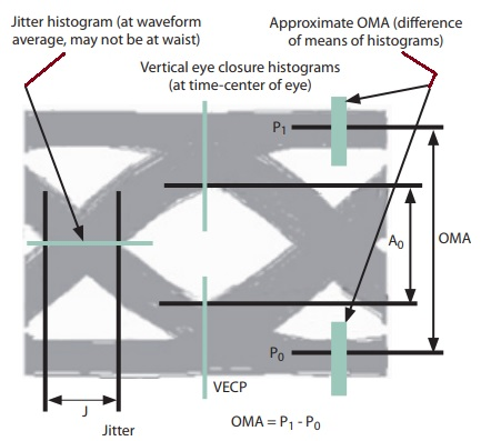
The extinction ratio is one of the parameters used to measure the quality of optical modules. The extinction ratio refers to the ratio of the optical power when the laser outputs a high level (i.e., all "1" codes) and a low level (i.e., all "0" codes). Through testing, it can be detected whether the laser is operating within the optimal bias point and the optimal modulation efficiency range. In addition, the optical modulation amplitude (OMA) is also an indicator to measure the power difference when the laser is turned on and off.
Both are detected by mainstream optical oscilloscopes. At the same time, the relative amplitude of the optical signal "1" level and "0" level can be seen in the extinction ratio detection. The larger the extinction ratio, the larger the relative amplitude, the stronger the optical signal can be received and distinguished, and the higher the receiving sensitivity. At the same time, the extinction ratio is inversely proportional to the optical power. During the test process, it can be found that the larger the extinction ratio, the smaller the transmitted optical power.
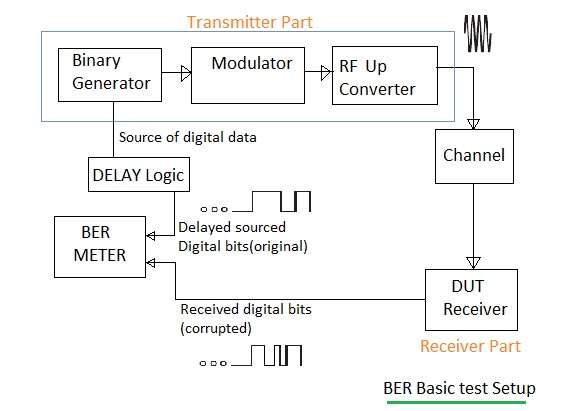
The bit error rate is one of the parameters that measure the ability of an optical module to correctly transmit code elements. The bit error rate refers to the ratio of the number of error code elements received after photoelectric conversion at the receiving end within a specified time to the number of code elements given by the output end of the bit error meter. The bit error rate test requires the standard receiving tube test unit to receive the optical signal with a pseudo-random signal output by the tested optical module, and use the standard receiving tube test unit to demodulate and compare to complete the bit error rate test.
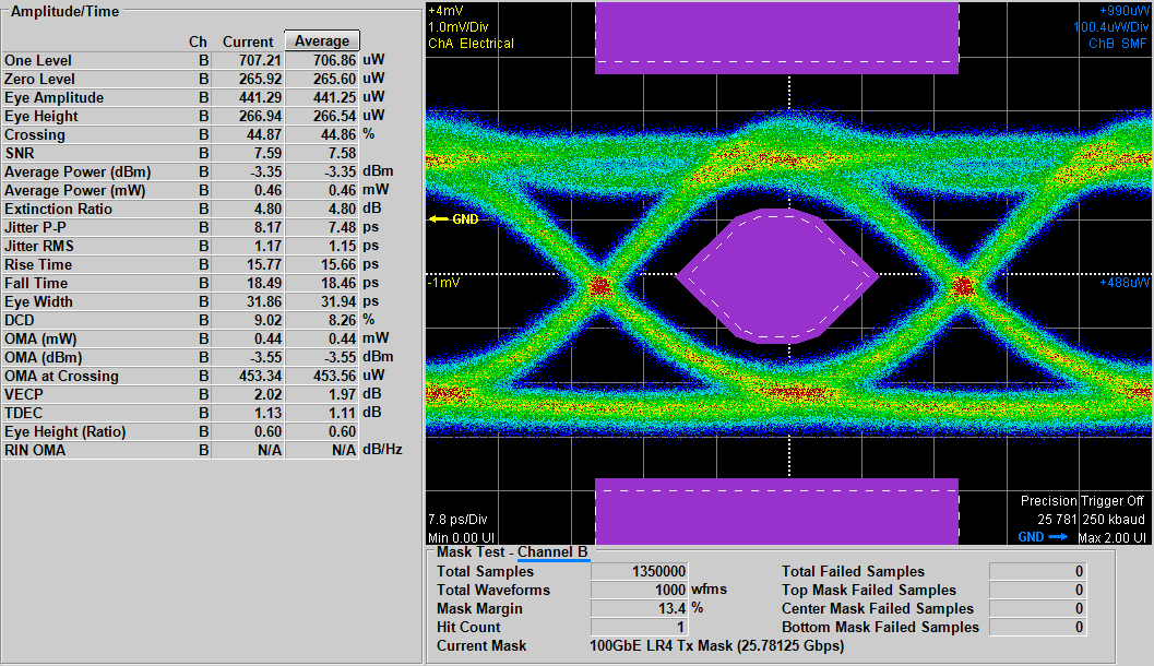
Eye diagram testing and adjustment is an important stage to ensure that the optical module obtains the best signal. The so-called eye diagram is formed by superimposing and accumulating all the captured waveforms according to every three bits through the persistence function of the oscilloscope. The digital signal quality of the optical module can be seen from the eye diagram test results. The performance of the optical module can be judged by carefully observing the eye height, eye width, jitter, duty cycle, etc. The larger the eye, the smaller the inter-code crosstalk, and the better the performance of the optical module.
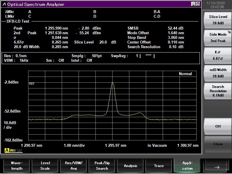
Since the optical modules used on the devices at both ends must emit the same wavelength to establish communication, the manufacturer must test the wavelength of the optical module before shipment to ensure that it is within the deviation range.
Generally, manufacturers use instruments such as spectrum analyzers to measure the center wavelength of the optical module, and the measured center wavelength value of the optical module will usually deviate from the standard value. Different types of optical modules have different deviations, but as long as the deviation is within the allowable range, it is recognized. If the tested value is inconsistent with the standard specification, the optical module is considered a defective product.
Manufacturers generally use optical aging chambers to simulate extreme conditions to test optical modules, thereby verifying whether the performance of the optical modules meets the standards. After the aging test is completed, the transmitter and receiver need to be tested to check whether parameters such as optical power, extinction ratio, and sensitivity meet the requirements.
Insert the optical module into the switch of the corresponding brand for testing. If the communication is normal, it means that the optical module has passed the test. If it cannot communicate, it means that the optical module is not compatible with it.
After each test item, the optical module needs to be inspected under a microscope to see if there is dirt and scratches on the module end face. If there is dirt, it needs to be cleaned. In fact, each test item involves inserting the optical module into a device or instrument, so the optical module is easily contaminated. Therefore, before shipment, the optical module needs to be placed under a microscope for inspection. If there is no dirt, it can be prepared for packaging and shipment, but if there is dirt, it needs to be cleaned.
The above tests are what qualified fiber transceiver manufacturers need to do. UnitekFiber will strictly control the quality of transceiver modules, and they will pass the above tests before shipment, so you can buy them with confidence. For any inquiries or further information, please don't hesitate to reach out to us at sales@unitekfiber.com.

